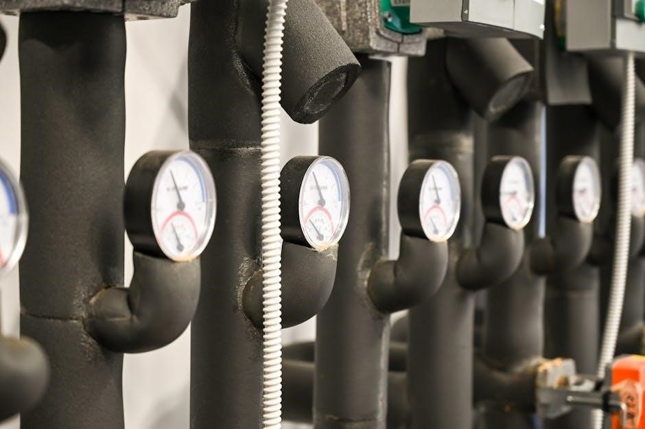
P&ID symbols are standardized graphical representations used in process industries to depict components like valves, instruments, and vessels in a clear, concise manner, ensuring universal understanding and application.
What are P&ID Symbols?
P&ID symbols are standardized graphical representations used in Piping and Instrumentation Diagrams to depict components, systems, and processes in industrial facilities. These symbols are essential for clear communication among engineers, operators, and technicians, ensuring consistency in design and operation. They represent various elements such as valves, pumps, instruments, and vessels, providing a visual language to illustrate process flows, interconnections, and control systems. Standardized by organizations like ISA and ANSI, these symbols are universally recognized, making them a critical tool in industries like oil, gas, and chemical plants. Their uniformity ensures accurate interpretation, enabling efficient system design, maintenance, and troubleshooting across industries.
Importance of P&ID Symbols in Process Industries
P&ID symbols are vital in process industries for ensuring clarity, safety, and efficiency. They provide a universal language, enabling professionals to understand complex systems at a glance. By standardizing representations of valves, instruments, and equipment, P&ID symbols reduce errors and misinterpretations. They are essential for designing, operating, and maintaining facilities, as they clearly illustrate process flows and interconnections. Accurate interpretation of these symbols enhances communication among teams, improves operational safety, and streamlines troubleshooting. Their importance extends to compliance with industry standards, ensuring consistency across projects and industries, which is critical for maintaining operational excellence and regulatory adherence in sectors like oil, gas, and chemicals.

Standard P&ID Symbols and Their Meanings
Standard P&ID symbols represent components like valves, instruments, and vessels, ensuring consistency and clarity in process documentation. These symbols are universally recognized and follow industry standards.
Valves and Piping Components
Valves and piping components are crucial elements in P&ID diagrams, represented by standardized symbols. Common valve symbols include gate, globe, ball, and check valves, each indicating specific functions like isolation or flow control. Piping components such as elbows, reducers, and bends are shown to depict the physical layout of the system. These symbols are standardized according to industry norms, ensuring consistency across designs. They are essential for understanding process flow, pressure control, and system maintenance. The use of universal symbols allows engineers and operators to interpret the diagrams accurately, facilitating effective communication and efficient system operation. Proper representation of these components is vital for process safety and reliability.
Instrumentation and Control Symbols
Instrumentation and control symbols are essential for representing measurement and control devices in P&ID diagrams. These symbols include pressure transmitters, temperature sensors, flow meters, and control valves, each denoting specific functions. They are standardized to ensure clarity and consistency across industries. Instrumentation symbols often include annotations like device tags and signal lines, indicating how data is transmitted and processed. Control symbols, such as logic gates and PID controllers, illustrate the automation aspects of the system. These symbols are critical for understanding process monitoring, automation, and safety mechanisms, enabling engineers to design and troubleshoot control systems effectively. Their accurate representation ensures seamless communication among stakeholders in process industries. Proper use of these symbols adheres to industry standards like ANSI/ISA-5.1-2009, ensuring universal interpretation and application.
Equipment and Process Vessels
Equipment and process vessel symbols represent tanks, reactors, heat exchangers, and other process equipment in P&ID diagrams. These symbols are standardized to depict the specific type of vessel and its connections. For example, a tank may be shown as a rectangular or cylindrical shape, while a reactor might include internal agitation symbols. Process vessels are often labeled with their design specifications and operating conditions. These symbols are crucial for understanding the layout and functionality of process systems, enabling engineers to identify equipment roles and interconnections. Their accurate representation ensures clarity in system design, operation, and maintenance, adhering to industry standards for consistency and universal interpretation.

How to Read a P&ID
Reading a P&ID involves identifying symbols, understanding interconnections, and interpreting process flow. Start by locating equipment, valves, and instruments, then trace piping and control systems to comprehend the system’s operation and design.
Understanding the Layout and Interconnections
Reading a P&ID begins with identifying the layout, which visually represents the process flow. Start by locating major components like equipment, valves, and instruments. Piping lines show material flow, with arrows indicating direction. Symbols for instruments, such as sensors and controllers, are connected via dashed lines representing electrical or pneumatic signals. Color-coding may differentiate fluid types or operating conditions. Understand how equipment interacts through interconnected piping and control systems. Familiarity with industry standards like ISA-5.1 ensures consistency in interpreting symbols and connections. Grasping the layout and interconnections is critical for operational safety, troubleshooting, and process optimization, making it the foundation of P&ID analysis.

Identifying Symbols and Their Functions
Identifying P&ID symbols requires understanding their standardized representations. Valves, pumps, and instruments each have unique symbols, while lines represent piping and connections. Instrument symbols often include abbreviations like “LT” for level transmitters. Dash lines denote control signals, distinguishing them from solid piping lines. Colors may highlight fluid types or operating conditions. Familiarity with standards like ISA-5.1 ensures accurate identification. Symbols are grouped logically, showing how components interact. This clear organization enables quick identification of system functions, making P&IDs essential for efficient process control, troubleshooting, and maintenance. Proper symbol recognition is critical for safe and effective system operation across industries.

Applications of P&ID Symbols in Various Industries
P&ID symbols are widely used in oil, gas, chemical, and power plants to design, operate, and troubleshoot process systems, ensuring safety and efficiency across industries.
Oil and Gas, Chemical, and Power Plants
P&ID symbols are crucial in oil and gas, chemical, and power plants for designing and maintaining complex process systems. These symbols represent components like valves, pumps, and instruments, ensuring clarity for engineers and operators. In the oil and gas industry, they help map hydrocarbon processes, while in chemical plants, they illustrate reactions and safety controls. Power plants use P&ID symbols to outline energy generation systems. Standardized symbols across these industries facilitate communication and compliance with safety regulations, making them indispensable for efficient and safe operations. Their universal recognition aids in troubleshooting and ensures system reliability.

Creating and Editing P&ID Symbols in PDF Format
Creating and editing P&ID symbols in PDF format involves using specialized software or libraries that support vector graphics and symbolic representations. Tools like AutoCAD, SmartDraw, or dedicated P&ID software provide comprehensive libraries of standardized symbols, ensuring consistency and accuracy. Users can drag-and-drop symbols, customize their properties, and arrange them to represent process flows. Editing features allow modifications, such as resizing, labeling, and connecting symbols with lines or arrows. PDF formats are widely used for sharing and reviewing diagrams due to their compatibility and scalability. Properly formatted P&ID symbols in PDF ensure clarity and professionalism, making them essential for documentation and collaboration in process industries.

Best Practices for Designing P&ID Diagrams
Designing P&ID diagrams requires adherence to standardized practices to ensure clarity and accuracy. Always use universally recognized symbols and follow industry standards like ISA-5.1 for consistency. Maintain a logical layout, grouping related components and using clear labels for equipment and instruments. Avoid overcrowding by balancing detail with readability. Ensure proper scaling and alignment to reflect the actual process flow. Regularly review and update diagrams to reflect system modifications. Use color-coding for differentiating piping systems or signal types. Cross-reference with other documents, such as PFDs, to ensure accuracy. Finally, document changes and maintain version control for traceability and compliance with regulatory requirements.
Challenges in Interpreting P&ID Symbols
Interpreting P&ID symbols presents challenges due to the complexity and variability of diagrams. One major issue is the lack of standardization across industries, leading to confusion. Symbols may differ slightly between companies, complicating understanding. Another challenge is the density of information, making it hard to trace lines and connections. Outdated diagrams that don’t reflect system modifications can cause errors. Additionally, the reliance on color-coding can hinder accessibility for color-blind individuals. Training and experience are crucial to overcome these challenges, ensuring accurate interpretation. Regular updates and adherence to universal standards can mitigate these issues, enhancing clarity and safety in process operations.
Future Trends in P&ID Symbol Standardization
The future of P&ID symbol standardization lies in digitalization and enhanced collaboration. Industry standards like ISA-5.1-2009 will evolve to incorporate new technologies, ensuring consistency across global projects. Digital libraries with intelligent symbols will streamline design processes, reducing errors. Cloud-based platforms will enable real-time collaboration, improving accessibility for engineers worldwide. AI and machine learning will aid in automating symbol recognition and validation, enhancing accuracy. Integration with Building Information Modeling (BIM) and Industry 4.0 technologies will further unify P&ID practices. These advancements aim to create a universal, dynamic standard, fostering innovation and efficiency in process industries. Standardization will continue to play a vital role in ensuring safety and clarity in complex systems.
P&ID symbols are crucial for clarity and safety in process industries. They provide a universal language, enabling effective communication among engineers, operators, and technicians. Standardized symbols ensure consistency, reducing errors and enhancing understanding. As industries evolve, the development of digital libraries and tools will further streamline P&ID creation and interpretation. The integration of technologies like AI and BIM will revolutionize how these diagrams are used. Ultimately, P&ID symbols remain a cornerstone of process design and operation, ensuring systems are designed, built, and maintained safely and efficiently. Their importance will only grow as industries continue to innovate and rely on precise visual representations.
